01
Twin parallel
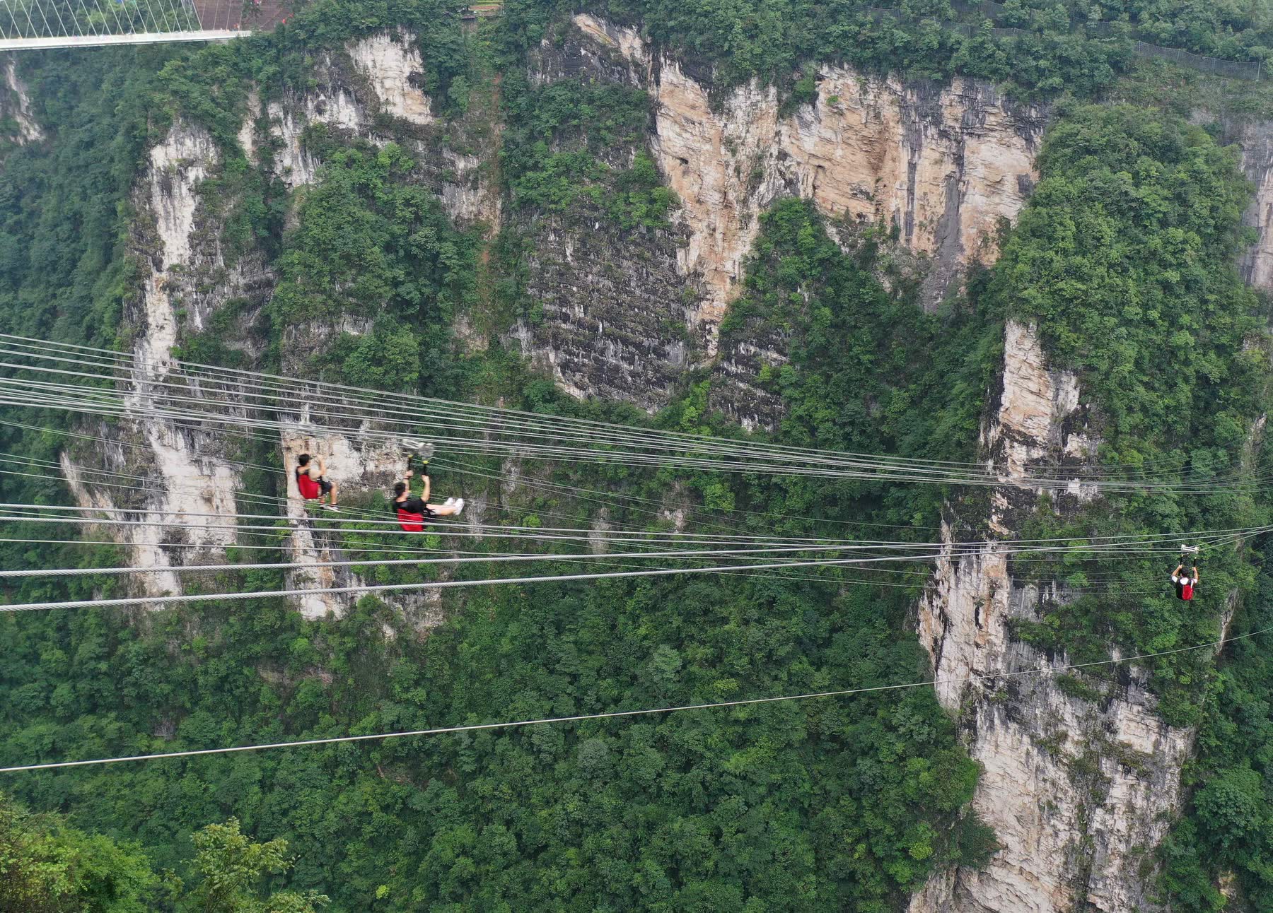
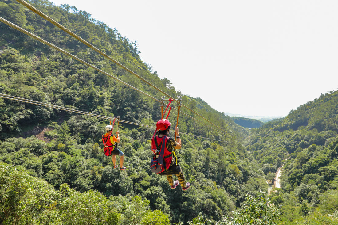
Two independent lines side by side. Friends ride together and the queue moves twice as fast as a single line — the usual choice for a first installation.
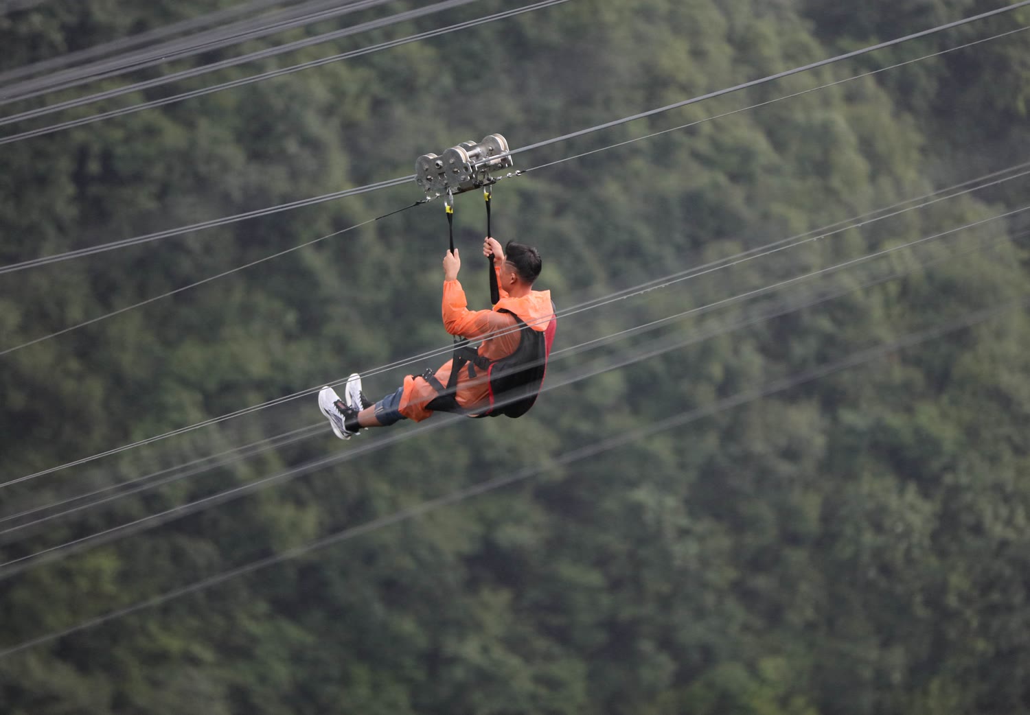
A rider on a full-body harness, a trolley on a galvanised load cable, a rubber brake and a buffer stop. Everything between the two stations is specified from your elevation profile.
The upper station sits higher than the lower one. The rider is clipped into a multi-point harness hanging from a trolley, and the trolley rolls down a pre-tensioned steel cable. No motor, no power on the line itself — the only energy input is the height difference you already have.
That makes the two things that matter the cable geometry and the stopping. We calculate both from your survey: where the cable sags, how much clearance that leaves over the ground, how fast the rider arrives, and how much distance the brake needs to bring them to a standstill.
These are the figures for a typical installation. Cable size, tension and station height are recalculated for every order against the actual site survey — they are not fixed catalogue values.
| Structure | Twin cable (load cable + safety cable) |
|---|---|
| Ride type | Straight-line, gravity driven |
| Lines per span | 2 standard; 4+ on request |
| Typical span | 150 m – 1500 m |
| Riders per trolley | 1 |
| Typical top speed | Up to 58.9 km/h |
| Drive | None on line — gravity |
| Trolleys & harnesses | 10 sets standard |
| Load cable | 6×19W+IWR-1870 B Z, galvanised |
|---|---|
| Cable diameter | Φ18 mm (site dependent) |
| Structural tube | Φ216 mm circular, hot-dip galvanised |
| Safety cable | Independent secondary on each anchor |
| Braking | Rubber deceleration unit + buffer stop |
| Anti-collision | Frame + sponge pad at lower station |
| Recovery | Winch system, manual or electric |
| Wind safety | Anemometer with stop threshold |
| Electrical | 380 V where powered recovery is used |
Values shown are the reference build. Final cable diameter, pre-tension, station height and braking distance are set per project after the site survey is reviewed.
Two independent lines side by side. Friends ride together and the queue moves twice as fast as a single line — the usual choice for a first installation.
Four or more parallel lines for high-throughput attractions. Each line carries its own trolley set, brake and inspection record.
Where the terrain drops in steps, the route can be split into consecutive spans with an intermediate platform between them.
We can give you a firm configuration and price once we know these. Without them any figure is a guess, and a guess on a zipline is a safety problem later.
An elevation survey or a topographical drawing shortens the engineering stage considerably, but we can start from a hand sketch with spot heights.
Send your site detailsSend span, drop and terrain. We reply with cable sizing, the hardware list and a quotation built around your site.